CSV3A and 3B: Installation Instructions
Note: Submersible motor manufacturers recommend using a flow inducer sleeve to be sure the motor is sufficiently cooled at low flows. Pressure differential across the valve cannot be more than 125 PSI.
Please read all instructions before beginning installation
Step 1
Be sure that the well has been pumped clean before the valve is installed. It is important that all lines including the pump, be flushed clean of debris. Turn off power to pump and drain system. This product creates back pressure, that is how it works. Back pressure is determined by the pump you are using. Be sure your piping between the pump and the Cycle Stop Valve is rated for that pressure.
Step 2
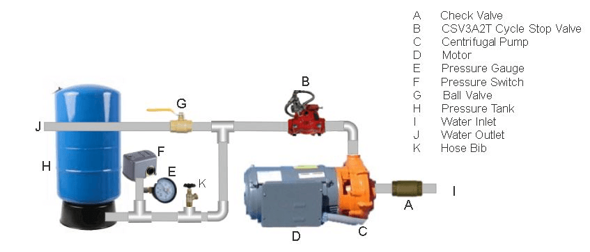
The valve should be installed horizontally with valve top/ID plate facing up. It should be downstream of the pump but before the pressure tank/pressure switch with all water outlets/demand downstream of the valve. Four inch and smaller valves can be installed vertically with flow going up, not down. Flow direction is indicated by the arrow on the valve (Note: There cannot be any water outlets between the pump and the valve (including gate valve, pressure relief valve, etc. If outlet lines exist between the well and the tank, the valve must be installed at the well head. Always keep in mind this is a pump control valve. All water pumped/demanded must first go through our valve for it to be able to control the pump).
Step 3
We recommend using teflon tape on threaded ends however most thread compounds are acceptable. All connections should be water tight.
Step 4
Pressure tank should be installed downstream of the CSV3A/B on a tee at a 90 degree angle to the main discharge line. Valve and pressure tank should be as close together as possible. There should be no more than 6-10' of piping between the valve and the pressure tank. Pressure tank pre-charge should be 5-10 psi lower than the pressure switch start point. A water line at least 8" or longer and no larger than tank inlet size should be used to connect the tank. Pressure switch must be installed on the line going into the tank, as close to base of the tank as possible. (closer to the tank than the main line). Pressure switch should never be installed directly on the main line.
Step 5
For start up, loosen the lock nut on adjusting stem of pilot valve (small valve attached to CSV3A/B). Make sure adjusting stem is loosened completely by turning counter clockwise until you feel it is no longer making contact with the spring. Set the pressure switch to desired settings. Cut off pressure must be at least 10 PSI higher than the desired valve set pressure (ie: 40/60 pressure switch, valve set at 50). Open a small water outlet to turn pump on. It is critical to allow at least 5GPM and not more than 10 GPM out of the system during valve setting procedure (approximately 1 standard 3/4" water hose). Now adjust the CSV3A/B to desired pressure by turning the adjusting stem on the pilot valve clockwise to increase pressure, and counterclockwise to decrease pressure. When pressure steadies at the desired system pressure, tighten the lock nut on adjusting stem of the pilot valve. Valve setting is complete.
Note: If water hammer occurs on pump start up, you must set valve pressure and cut in pressure the same. For example...40/60 pressure switch, valve set at 40.
Step 6
Close off the water outlet making sure no water is being demanded. The pressure tank will begin to fill at approximately 5 gpm. As pressure tank slowly fills, pressure in the system will increase until the pressure switch turns the pump off.
California Proposition 65 Warning: This product contains chemicals known to the state of California to cause cancer and birth defects or other reproductive harm. (Installer: California law requires that this warning be given to consumer.)