CSV1A: Installation Instructions
Preparation and Installation
- It is important that the well has been pumped until clean before any valve installations. You do not want to fill the valve with debris/drilling mud/sand/pvc shavings, etc. (Note: Multiple pump systems need a CSV for each pump). Turn off power to pump and drain system. This product creates back pressure, that is how it works. Back pressure is determined by the pump you are using. Be sure your piping between the pump and the Cycle Stop Valve is rated for that pressure.
- The CSV1A must be installed prior to any tee offs. It can be installed in any position as long as the flow arrow is pointing away from the pump. Correct order of installation should be: Pump - CSV1A - All other outlets including the tank/switch. The only valve allowed between the pump and the Cycle Stop Valve is a check valve. (Always keep in mind this is a pump control valve. All water pumped/demanded must first go through our valve for it to be able to control the pump). Direction of flow is indicated by the arrow on the valve itself for proper positioning.
-
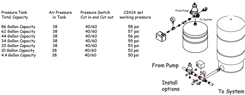
The diaphragm style pressure tank should be installed downstream of the CSV1A. (NOTE: All side and bottom ports on the CSV1A are downstream ports.) There are two options: The tank can be installed/plumbed into the 3/4" port on the bottom of the CSV1A valve with the pressure switch/gauge/presure relief valve installed on the two 1/2" side ports....or the tank can be tee'd off of the main line via a standard tank Cross or tank tee. Pressure switch and other controls can either be installed on the tank tee or tank cross.
Note: Do not install pressure switch directly on main line away from pressure tank. Pre-charge pressure in the tank should be 2-5 psi lower than pressure switch start point.
- Install using teflon tape on all threads. Seven to ten wraps of teflon tape is usually sufficient. All connections should be water tight.
Setting the Valve
- Be sure the adjustment stem is loosened counter clockwise almost all of the way out (You might have to loosen the lock nut if it is tight).
- Turn on enough water to dump your pressure tank and cause your pump to come on.
- Once the pump has come on, adjust your demand to 2-3 gpm (This reduced demand is important. You do not want to set the valve with more gpm going through it than this). With the adjustment stem loosened all of the way out, the valve is going to try to hold a low pressure of 15-25 psi or so. Wait a few moments after each adjustment for the valve to react and the pressure to level off. Each full round on the adjustment stem is approximately 13 PSI adjustment.
-
The CSV1A is adjusted by turning the adjustment stem clockwise to increase downstream pressure and counter clockwise to decrease downstream pressure. Adjust the CSV1A until the pressure steadies at your desired working pressure. Tighten the lock nut. The valve is set.
The CSV1A works with your pump sytem using pressure. The CSV1A has to be set within your existing system pressure parameters to work correctly. The pressure tank pressure needs to be 2-5 psi lower than your pressure switch cut in pressure. The pressure switch cut off pressure needs to be higher than the CSV1A working pressure. How much higher depends on your pressure tank size. See chart below for your specific tank/pressure switch recommendations/examples.